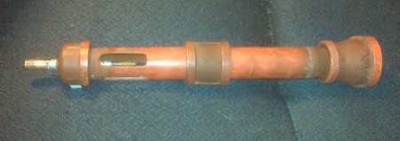
In the process of diagnosing my problems I’ve addressed air intake, tube and exit gas velocity and flame stability. Here is the end result as it deviates from my initial Propane Burner post.
- Larger air intakes than initial size
- Tip pushed forward
- Simplified Flame Holder
- Choke
- Paint Job

Larger air intakes than initial size
While this was done as an attempted solution at overcoming a tube velocity issue (easier airflow) the end result at this point yields a great fuel/air mix at all pressures. So I can’t say that it’s definitely needed, but it does work and I’d recommend it.
The four current slots are roughly 1 3/4″” x 1/2″, the edges angle inward to the tube to provide the largest cross-sectional area and least amount of drag, and the far end near the tip has a dramatic scoop into the tube. The tip-end of the slot is also squared off to reduce unnecessary turbulence at a point that we need as much velocity as possible.
Cross-sectional area of the pipe: 0.5 in * 0.5 in * 3.14 = 0.785 in^2
Surface area of the slots: 1.75 in *.5 in *4 = 3.5 in^2
Check! Plenty of low-drag air intake, even if 100% of the tube volume needed to be air, the slots can accommodate that.
Tip pushed forward
The tip in the initial burner design was definitely too far back. While it worked, I was having a hard time generating the velocity necessary to pull enough air into the tube resulting in a bad mix.
To push the tip forward, I replaced the 2″ brass 1/8″ nipple with a 3″ nipple. This new variety wasn’t nearly as tight a fit as the previous one. I fit the tip by wrapping heavy aluminum sheet around the threads and wedging it into the brass tube. Afterwards I did the normal soldering job as before. Since more of the nipple is exposed, I also tapered off the end near the tip and eliminated the threads to promote smoother airflow.
I’ve kept the burner tip pulled back about 1/2″ from the outer edge of the forward slot edge to maximize the air-path while still generating a lot of suction via venturi action.
Simplified Flame Holder
My initial flare was having problems keeping the flame steady, and the experimental grill flame-holder choked off air entrainment far too much. A less restrictive grill may have done the trick, and grinding out a wider flare (lessening the ratio) did present a fairly stable flare as much due to the new-found turbulence generated by the knobs and divots in the refractory material after grinding as anything else. Unfortunately, the expanded flare had a limited pressure range that it worked in, probably because the turbulence was a bit chaotic and could “blow out” the flame at low and high pressures.
Thinking about the effects of turbulence, I realized that the fan-grill was a failure for the simple reason that the grill itself blocked off a good portion of the cross-sectional area, and the parts that were still open became “dense” with fuel and airflow, making it harder yet for the fuel in the tube to push through. The upshot is that fuel velocity decreased, reducing the venturi effect, limiting the amount of air pulled into the tube. This caused a decent amount of the fuel to burn rich with incomplete combustion. What would happen if the grill was installed onto a larger cross-sectional area where it wouldn’t be choking off air?
So that got me thinking about replacing my coupling with a 1″ -> 1 1/4″ reducer as a mounting point for another flame holding device. After looking closely at the reducer I realized that it had the essential widening action of a flare (slow down the gas) as well as a turbulence generator in the form of the larger threads at the exit. I suspected that the reducer itself might make a fine flame holder with absolutely no tinkering…. and it does! Ah, the irony.
I MAY grind down the inner-most threads slightly to try to step the turbulence up gradually and improve speed, but at this point it’s working… do I really want to tinker?
Choke
Frankly, the choke doesn’t seem to be necessary at all. In the current configuration, I’m getting a good fuel/air mix across the range of gas volumes by simple venturi action. If you’ve gotten this far without making one, save yourself some trouble and see if you actually need it first.
Paint Job
To keep corrosion down on the cast iron pipe, I decided to coat it with Rustoleum’s 2000 degree F paint. While I shouldn’t push this burner into the center of the firing chamber, this should help with high oxidation of the iron surface due to heat exposure.
The part most at risk is the flame holder, but at $3 and no real effort I’m not terribly worried. Still, why replace at all if you don’t need to?
This was supposed to be red. The paint itself was closer to an orange. The color was ok up to 400 degrees, but by the time I got to 550 it started discoloring the paint job by depositing a layer of soot onto the paint. I can tell because the flare was sitting on a rack… where the wires touched the flare and protected it from fumes, it’s bright red. The brass connections also had coating on them, but it came right off the slick metal. The painted burner looked a bit like aged bronze at the end, actually.
On further thought, the problem may be the black iron pipe itself! Coated with an oil to inhibit rusting, if the temp gets high enough it’s bound to burn off. If you’re going to paint and want the natural coloration I’d strongly recommend doing a pre-heat treatment before applying any to burn off anything that is already on the pipe
I decided to take a Mr. Clean Magic Eraser to the edges of the tip assembly, and sure enough, underneath was the color. I cleaned off the “edges” of the caps, flare, and choke, and did what I could to clean down the main body. The end result is a “smokey fire” effect. Not unpleasant… looks like this thing started off bright orange about 50 years ago. 🙂 Every time I look at it I think “Half-Life.”
The surface is pretty tough and should keep water vapor and oxygen away from the surface. I’m enthusiastic about the increased lifespan.
Update: I ultimately decided to taper down the exit threads on the flame retainer (thinner threads toward the tube) to reduce turbulance and back pressure. Doing to ultimately let me dial down the pressure to a soft gentle breeze without huffing. The soft blue flame at that pressure eminates from the end and drifts up lazily. To keep the flame blue at that pressure you DO need a choke, otherwise the flame goes yellow and sooty.

[…] Burner Modifications […]
dude, awesome site, i couldnt understand ron reils site, sort of lacking in newbie-how-2 procedure pics, your site made it so easy to understand. :D, so how would you say the tweco welding tip compares against the plain brass plug for a jet?
Glad that you like it. Too many sites just give dimensions, etc, without explaining the “whys” and I like to understand what’s going on. Not a whole lot of “step-by-step” instruction either so I figured I’d share my trial and error while figuring it out… save people some trouble. 🙂
I never tried the straight plug tip. I strongly suspect that tweco vs plug won’t make a difference in the old Reil burner, but that it helps the mongo types. The reason is that the tip is inline with the pipe. The wider the tip the less area for air to flow into the pipe from the vents… the tapered tip basically results in less constriction as the air approaches the jet, which should mean less drag and better air/fuel ratios. The old reil “bell” burner has a lot of air intake, so it’s probably irrelavant.
That said, if you’re having trouble finding the tapered tips you could probably get by just fine by using a dremel or grinding wheel to taper the blunt plug by hand. You’d want to polish it up to reduce friction afterwards. I did a little hand-tapering on the brass tube that holds the tip to try to improve performance (or rather, I assume that it could only help, so tapered it before inserting the tip.)
Hi kcrucible,
I found your web page by searching for gas burner information on iforgeiron.com.
You have a great description on how to build a burner.
I have built 4 Reil style burners, and they work very well to heat up my forge. I only ever use 2 burners, so I took the other 2 out and use them to experiment with new flares and chokes and such. Lately I have been thinking about ways to upgrade from my rather primitive gas jets, which are holes drilled into the side of a brass pipe nipple. Using welding tips looks like an easy & cheap way to go.
I am seeing a lot of good ideas in your work, which I am looking forward to trying out.
My most recent improvement to the Reil burner was to make an improved flare, by taking a 3/4″-1″ coupling, and boring out the threads in the 1″ end to a 5 degree taper.
http://www.iforgeiron.com/topic/29889-comparing-3-types-of-nozzles/
This resulted in an incredibly stable flame over 0-30+ psi pressures. My gauge maxes out at 30psi, so I couldn’t verify at higher pressures.n
Finally, if I may, I noticed a minor math error in your text:
“Cross-sectional area of the pipe: 1 in * 1 in * 3.14 = 3.14 in^2”
The area of a circle is A = pi*r*r where r is radius, not diameter. Therefore, the proper calculation should be:
0.5in * 0.5in * 3.14 = 0.785in^2
All this means is that your air intake slots provide more tha enough unrestricted air flow for your burner!
Thanks for publishing your work.
All the best
Markus
You are correct about the area calculation. I must have been in a hurry and not really thinking it through.
I’m glad that you found the information useful. I spent so much time researching the issue from all of the different sites and trying to figure it out that I figured that I may as well post the information for other people to use and save them the trouble. It also seemed a good place to “think out loud” as I tried different things.
It sounds like your coupling-flare is basically what I ended up with. It works surprisingly well.
I had a blast making my burner and furnace. The irony is that I haven’t actually used the furnace for anything really yet… just an initial maiden-voyage burnout and then life got in the way. I’m hoping to get back into the forging experimentation come this spring.
At the risk of sounding silly… What kind of Silver Solder did you use? I applied silver solder that I had for copper water pipes but I am not sure that this has a high enough melting point to work for this.
Thanks for your help!
Brian
That’s what I used. I wasn’t sure it was going to work either, but it’s fine. The air velocity through the air intakes past the nozzle keeps everything cool.
Ideally I’d have a higher temp material, but it was what I had on-hand and it worked.
I just let my torch for the first time, It did great. I appreciate your reply on the solder and this your posting the burner details!!!! 🙂
You’re welcome. Congratulations!